Canalblog
Suivre ce blog Administration + Créer mon blog

telecommunication

22 juin 2016

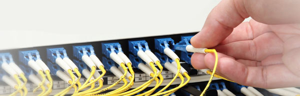
Introduction to Cisco Gigabit Ethernet SFP Module

Gigabit Ethernet represents a merging of 8022.3 Ethernet and ANSI X3Tll fiber channel technology. There are five physical layer standards for Gigabit Ethernet using optical fiber (1000BASE-X), twisted pair cable (1000BASE-T), or shielded balanced copper cable (1000BASE-CX). Among them, 1000BASE-X is used in the industry to refer to Gigabit Ethernet transmission over fiber, where options include 1000BASE-SX, 1000BASE-LX, 1000BASE-LX10, 1000BASE-BX10 or the non-standard -EX and -ZX implementations. Cisco, the largest networking company in the world, provides a range of SFP transceivers for Gigabit Ethernet applications, including 1000BASE-T SFP, 1000BASE-SX SFP, 1000BASE-LX/LH SFP, 1000BASE-ZX SFP, or 1000BASE-BX10-D/U SFP on a port-by-port basis. This post mainly introduces these five Cisco Gigabit Ethernet SFP modules for your reference.

Cisco 1000BASE-SX SFP

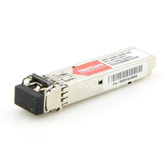
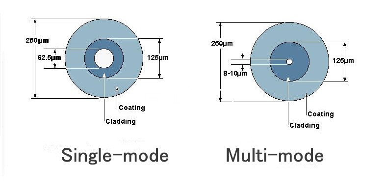
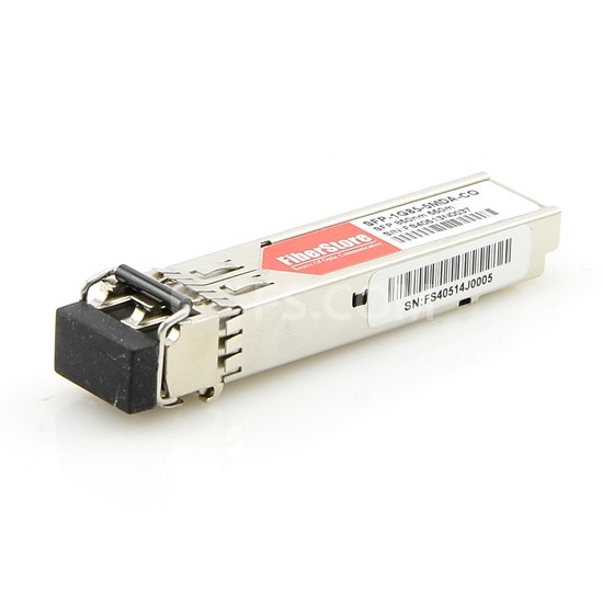
The 1000BASE-SX SFP is compatible with the IEEE 802.3z 1000BASE-SX standard. It operates on legacy 50 μm multimode fiber links of up to 550 m and on 62.5 μm FDDI (Fiber Distributed Data Interface ) grade multimode fibers up to 220 m. It can support up to 1 km over laser-optimized 50 μm multimode fiber cables. GLC-SX-MM and SFP-GE-S are the two earliest configurations of Cisco 1000BASE-SX SFP. Later GLC-SX-MMD (as shown in following picture) with DOM functionality appears.

GLC-SX-MMD

Cisco 1000BASE-LX/LH SFP

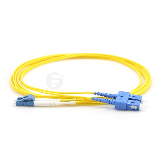
The 1000BASE-LX/LH SFP is compatible with the IEEE 802.3z 1000BASE-LX standard. It operates on standard single-mode fiber optic link spans of up to 10 km and up to 550 m on multimode fibers. When it is used over legacy multimode fiber type, the transmitter should be coupled through a mode conditioning patch cable. This transceiver is joint with dual LC/PC connector. And the transmit and receive wavelength ranges from 1270 nm to 1355 nm.

Cisco 1000BASE-EX SFP

The 1000BASE-EX SFP operates on standard single-mode fiber optic link spans of up to 40 km. A 5-dB inline optical attenuator should be inserted between the fiber optic cable and the receiving port on the SFP at each end of the link for back-to-back connectivity. And the transmit and receive wavelength ranges from 1290 nm to 1335 nm.

Cisco 1000BASE-ZX SFP

The 1000BASE-ZX SFP operates on standard single-mode fiber optic link spans of up to approximately 70 km. This transceiver provides an optical link budget of 21 dB, but the precise link span length depends on multiple factors such as fiber quality, number of splices, and connectors. When shorter distances of SMF (Single-mode Fiber) are used, it might be necessary to insert an inline optical attenuator in the link to avoid overloading the receiver. A 10-dB inline optical attenuator should be inserted between the fiber optic cable plant and the receiving port on the SFP at each end of the link whenever the fiber optic cable span loss is less than 8 dB.

Cisco 1000BASE-BX10-D/U SFP

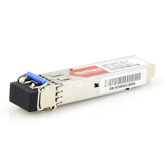
The 1000BASE-BX-D/U SFP is compatible with the IEEE 802.3ah 1000BASE-BX10-D and 1000BASE-BX10-U standard. It operates on a single strand of standard SMF. A 1000BASE-BX10-D device is always connected to a 1000BASE-BX10-U device with a single strand of standard SMF with an operating transmission range up to 10 km. The communication over a single strand of fiber is achieved by separating the transmission wavelength of the two devices. That is to say, the 1000BASE-BX10-D transmits a 1490-nm channel and receives a 1310-nm signal, whereas 1000BASE-BX10-U transmits at a 1310-nm wavelength and receives a 1490-nm signal. Then a WDM (Wavelength Division Multiplexing) splitter integrates into the SFP to split the 1310-nm and 1490-nm light paths.

Conclusion

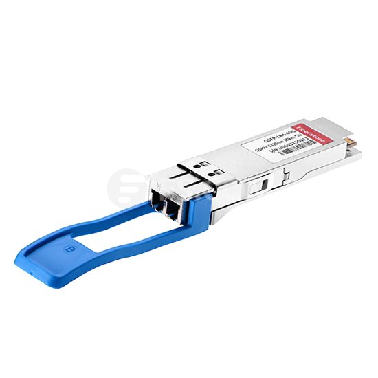
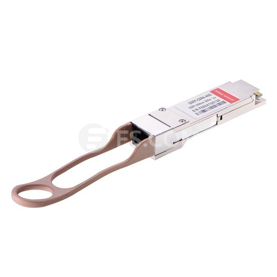
These Cisco SFP transceivers offer a convenient and cost effective solution for the adoption of Gigabit Ethernet in data center, campus, metropolitan area access and ring networks, and storage area networks. Besides, Cisco also provides other transceiver modules with high performance, such as 40GBASE-CSR4 QSFP+ transceiver (Cisco QSFP-40G-CSR4), 40GBASE CFP transceiver (Cisco CFP-40G-LR4), 100GBASE CXP transceiver (CXP-100G-SR10), etc. These Cisco transceivers can support Ethernet, Sonet/SDH and Fiber Channel applications across all Cisco switching and routing platforms.

Publicité
Publicité
17 juin 2016

How to Manage Fiber Optic Patch Cords?

With the greatly increasing demand for high-speed enterprise networks, fiber optic patch cords with high density are needed. And with the limited space available in wiring closets and equipment rooms, fiber optic patch cord management is very crucial. Generally, good fiber optic patch cord management can not only achieve optimum performance and reliability, but also minimize costs related to moves, adds and changes. Usually there are four parts in fiber optic patch cord management, including planning, preparation, patching, and validation. This article will illustrate how to manege fiber optic patch cords from these four aspects.

fiber optic patch cord

Planning

Before making cabling decisions, you need to obtain all necessary information about your cabling infrastructure. As is known to all, different fiber cablings have different specifications and design demands. So your fiber patch cords must match the installed cabling. First of all, choosing a cord of the correct length, which determines the best route between its points of connection. Once having established the best route for the cord, you can figure out the required length by adding the horizontal and vertical distances. And choose fiber optic patch cords with correct connector types. There are many kinds of fiber optic patch cables with different connectors, such as LC patch cable, SC patch cable, ST patch cable (as shown in following picture), etc. Next avoid excessive slack and provide a neat appearance when selecting a cord to make a cross connection. Finally, ensure you have cords of the right length available and that panels are fitted with correct cable management accessories. In general, a horizontal patch cord management guide is needed for every two rack units, depending on the type of optical patch panel or lightguide interconnect unit (LIU).

ST patch cable

Preparation

The preparation before performing administration activities is very essential, which can minimize disconnect time. Good preparation includes administrative records study, cord inspection, and cleanliness. Firstly, you should locate the ports that must be connected or reconnected and ensure technicians have clear information on what they need to do, including labeling information for the ports involved. Then you need to ensure fiber optic patch cords are of the right type and inspect them for physical damage, such as stress marks from bending on the sheath, pullout of fibers from the connector and cracks or scratches on fiber end. Finally, since cleanliness is vital in fiber optic connections, so special care is needed to ensure that fiber optic patch cords are clean and in good condition. That is to say, you should pay attention to the cleanliness of connector ends on patch cords, connector ends on panels, and connector ends on network equipment.

Patching

Kinks, snags, pinches and poor contacts can dramatically reduce the performance of fiber patch cords. To avoid these problems during the patching process, there are four factors you should take into consideration: bend radius, cord pulling and stress, bundling, and routing cords. Firstly, the minimum bend radius of fiber optic patch cords varies with cord diameter. So you should have an understanding of bend radius for different fiber optic patch cords. Then be careful not to use excessive force in the course of the patching process. This can stress cords and connectors, reducing their performance. Thirdly, when bundling fiber cords, do not tighten ties beyond the point where individual cords can rotate freely. Use only products manufactured for this purpose, and consider the use of products that can be reused without the use of tools. Finally, if the existing cord is the right length, it may be possible to reuse it. If this is the case, remove the cord completely and rerun it in through the cable pathways. This is the only sure way to ensure there are no tangles, kinks or strains.

Validation

After making the appropriate patching, it is the time to make a final visual check on connections. When patch panels are mounted in enclosures, ensure they are securely closed and locked, making sure that cord slack is not snagged or pinched by the doors. The final step is to update the documentation to the as-built configuration and close the work order associated with the completed change request.

Conclusion

A strong and reliable fiber optic patch cord management can increase the reliability and flexibility and decrease the cost of network operation and maintenance. When managing your fiber optic cords, you should follow the above four steps: planning, planning, preparation, patching, and validation. Only by obeying these four aspects strictly can a successful fiber optic patch cord management be obtained.

15 juin 2016

An Overview of Cisco SFP Transceiver Modules

SFP transceiver modules are hot-pluggable devices that plug into module sockets. These transceivers connect the electrical circuitry with the optical or copper networks. You can use any combination of SFP modules that your device supports. Cisco, the largest networking company in the world, has manufactured many kinds of SFP modules that support Ethernet, Sonet/SDH and Fiber Channel applications across all Cisco switching and routing platforms. To have a better understanding of Cisco SFP transceiver modules, we can divide these transceivers into three types: Cisco Fast Ethernet SFP modules, Cisco Gigabit Ethernet SFP modules, and Cisco CWDM SFP modules. This article will make an introduction to these three types of Cisco SFP modules for your reference.

Cisco Fast Ethernet SFP Modules

The Cisco 100BASE-X SFP devices are mainly plugged into Fast Ethernet ports, dual-rate Fast/Gigabit Ethernet ports, or Gigabit Ethernet ports of a Cisco switch or router, linking the port with the fiber cabling network. Cisco offers a range of Fast Ethernet SFP modules, including 100BASE-FX SFP, 100BASE-LX10 SFP, and 100BASE-BX10 SFP, etc. The Cisco 100BASE-FX SFP modules (as shown in following picture) operate on ordinary multimode fiber-optic link spans of up to 2 km. The Cisco 100BASE-LX10 SFP modules operate on ordinary single-mode fiber optic link spans of up to 10 km. While the Cisco 100BASE-BX10 SFP modules operate on ordinary single-mode single strand fiber optic link spans of up to 10 km. Besides, Cisco offers one type of 100M SFPs for Fast Ethernet SFP (FE) port.

Cisco 100BASE-FX SFP module

Cisco Gigabit Ethernet SFP Modules

Cisco offers a range of SFP transceivers for Gigabit Ethernet applications. These small, modular optical interface transceivers offer a convenient and cost effective solution for the adoption of Gigabit Ethernet in data center, campus, metropolitan area access and ring networks, and storage area networks. There are many SFP modules for Gigabit Ethernet applications, such as 1000BASE-T SFP, 1000BASE-SX SFP, 1000BASE-LX/LH SFP, 1000BASE-ZX SFP, or 1000BASE-BX10-D/U SPF on a port-by-port basis, etc. Among them, the 1000BASE-T SFP modules operate on standard Category 5 unshielded twisted-pair copper cabling of link lengths of up to 100 m. The 1000BASE-SX SFP modules, such as MA-SFP-1GB-SX 1000BASE-SX SFP transceiver (as shown in following picture) and Cisco GLC-SX-MMD 1000BASE-SX SFP transceiver, operate on multimode fiber link spans of up to 550 m. And the 1000BASE-LX/LH SFP mudules operate on standard single-mode fiber optic link spans of up to 10 km and up to 550 m on multimode fibers. In addition, there is also one type of 100M SFPs for Gigabit Ethernet (GE) SFP port.

MA-SFP-1GB-SX 1000BASE-SX SFP transceiver

Cisco CWDM SFP Modules

The Cisco CWDM SFP modules are hot-swappable input/output devices that plug into an SFP port or slot of a Cisco switch or router, and link the port with the fiber optic network. The Cisco CWDM SFP solution has two main components: a set of SFP pluggable transceivers, and a set of different Cisco CWDM passive multiplexer/demultiplexer or OADMs. These CWDM SFP modules come in wavelengths that range from 1470 nm to 1610 nm. They allow enterprise companies and service providers to provide scalable and easy-to-deploy Gigabit Ethernet and Fiber Channel services in their networks. These products enable the flexible design of highly available and multiservice networks.

Conclusion

Fiber optic technology has become an indispensable component for network backbone and other applications. At the same time, highly complex transceivers that require a large amount of intricate configurations are in demand. Cisco SFP transceiver modules provide a rich set of choices in terms of speeds, protocols, reaches and supported transmission media. These industry-standard Cisco SFP modules, such as Cisco Fast Ethernet SFP modules, Cisco Gigabit Ethernet SFP modules, and Cisco CWDM SFP modules, greatly meet customers’ requirements in data center, campus, metropolitan area access and ring networks, and storage area networks.

10 juin 2016

An Introduction to Cisco 40GE QSFP+ Transceiver

QSFP+ (quad small form-factor pluggable plus) is a compact, hot-pluggable transceiver used for network servers, interface cards or switches. Compared with SFP, QSFP+ transceiver increases the port-density of 3-4 times and integrates 4 independent 10 gigabit per second data lanes in each direction to provide 40Gbps bandwidth. A variety of Cisco QSFP+ transceivers are introduced into the market, such as Cisco QSFP-40G-LR4, Cisco QSFP-40G-SR4, Cisco QSFP-40G-CSR4, Cisco QSFP 40G BiDi, Cisco QSFP-40G-PLR4, etc. This post mainly introduces four Cisco 40GE QSFP+ transceivers, including: Cisco QSFP-40G-LR4, Cisco QSFP-40G-SR4, Cisco QSFP-40G-CSR4, Cisco QSFP 40G BiDi.

Cisco QSFP-40G-LR4

The Cisco QSFP-40G-LR4 40GBASE-SR4 QSFP+ transceiver supports link lengths of up to 10km over a standard pair of G.652 single-mode fiber with duplex LC connectors. 40 Gigabit Ethernet signal is carried over four wavelengths. Multiplexing and demultiplexing of the four wavelengths are managed within the device. This Cisco QSFP+ transceiver supports 40 Gigabit Ethernet and OTU3. In addition, this transceiver has diagnostic features, providing real-time monitoring of transmitted optical power, received optical power, laser bias current, etc. It is optimized to 40 Gigabit Ethernet switches and routers.

Cisco QSFP-40G-LR4

Cisco QSFP-40G-SR4

The Cisco QSFP-40G-SR4 40GBASE-SR4 QSFP+ transceiver can be used in 4x10G mode for distances of up to 100m on OM3 and 150 m on OM4 fibers. It primarily enables high-bandwidth 40G optical links over 12-fiber parallel fiber terminated with MPO/MTP multifiber connectors. Generally the 4x10G connectivity is obtained by using an external 12-fiber parallel to 2-fiber duplex breakout cable, which connects the 40GBASE-SR4 transceiver module to four 10GBASE-SR optical interfaces. This worry-free 4x10G mode operation is enabled by the optimization of the transmit and receive optical characteristics of the Cisco 40GBASE-SR4 to prevent receiver overload or unnecessary triggering of alarm thresholds on the 10GBASE-SR receiver. This transceiver is optimized to guarantee interoperability with any IEEE 40GBASE-SR4 and 10GBASE-SR.

Cisco QSFP-40G-CSR4

The Cisco QSFP-40G-CSR4 40GBASE-CSR4 QSFP+ transceiver is an extension product from Cisco QSFP-40G-SR4 40GBASE-SR4 QSFP+ transceiver. It extends the reach of the IEEE 40GBASE-SR4 and can achieve distances of up to 300 meters with OM3 fibers and 400 meters with OM4 fibers. The transceiver can be used for native 40G optical links over parallel cables with MPO/MTP connectors. Or it is used in a 4×10G mode with parallel to duplex fiber breakout cables for connectivity to four 10GBASE-SR interfaces. Each 10-gigabit lane of this transceiver is compliant to IEEE 10GBASE-SR specifications. This transceiver is optimized to guarantee interoperability over the complete specification range of 10GBASE-SR.

Cisco QSFP-40G-CSR4

Cisco QSFP 40G BiDi

The Cisco 40G BiDi QSFP+ transceiver is a pluggable optical transceiver with a duplex LC connector interface for short-reach data communication and interconnect applications. It consists of two 20-Gbps transmit and receive channels in the 832nm to 918nm wavelength range, enabling an aggregated 40-Gbps link over a 2-strand multimode fiber connection. This transceiver can be reused in the existing 10 Gigabit duplex MMF infrastructure for migration to 40 Gigabit Ethernet connectivity. Besides, it supports link lengths of 100m and 150m on laser-optimized OM3 and OM4 multimode fibers, respectively. Generally, this transceiver is compatible with the QSFP MSA specification, which allows customers to use it on all QSFP 40-Gbps platforms.

Conclusion

40G Ethernet networking which supports higher bandwidth is the new trend for big data center. Of all the 40G optical options, these Cisco 40GBASE QSFP+ transceivers offer high-density and low-power 40 Gigabit Ethernet connectivity options for data center. Cisco QSFP-40G-LR4, Cisco QSFP-40G-SR4, Cisco QSFP-40G-CSR4, and Cisco QSFP 40G BiDi , these QSFP+ transceivers have different applications and can meet different needs. All you need to do is choose the suitable one for your unique applications.

6 juin 2016

Why Choose Fiber Optic Cables in AV Applications?

As audio and video technologies continue to evolve, AV systems are continuously challenged with supporting high resolution video, audio, and control signals. Fiber optic cables, powerful media for AV application, offer the ability to address several needs and challenges beyond the scope of traditional coax or twisted pair infrastructures. This post will mainly introduce four advantages for the installation of fiber optic cables in AV applications.

High Resolution Video, Audio, and Control Signals

Fiber optic cables are low-loss channels that enable transmission of high resolution video, audio, and control signals over long distance. Losses in fiber optic cables are 0.2 to 3.5 dB/km, compared to 60 dB/km for legacy RG6 coaxial cable at 100 MHz. The low-loss nature of single-mode fiber cables can enable transmission of WQXGA 2560x1600 video signals up to 30 km. Due to these advantages, fiber optic cables are widely used in campuses, sports stadiums and large office buildings, etc. Besides, installing fiber optic cables with extremely high bandwidth can ensure that future applications can be addressed with today’s fiber installations.

Easy to Install

Fibers consume very little space in conduit and cable trays, and are easy to pull. For example, duplex fiber optic cable can transmit high resolution video signals but is only a fraction of the size of a coaxial cable. Because of fiber optic cables’ small size, the installation is much easier especially in medical applications where there is often insufficient space for thicker cables. Besides, today’s field termination kits make fiber easier to terminate than other types of cabling. Simply striping, cleaving, and inserting fibers into fiber optic connectors, you can get a high quality, reliable splice in minutes. And you can also choose pre-terminated fiber cables, such as LC to SC single mode fiber patch cable or LC to LC multimode fiber optic patch cable (as shown below). The connectors you specify are pre-terminated for you, and the fiber cables you specify are cut to the proper length that you need. When the installation is over, you can just plug and play fiber optic system.

LC to SC single-mode fiber patch cable

Safe for Sensitive and Hazardous Environments

Unlike copper cables, fiber optic cables are largely comprised of glass, which does not carry electrical current, radiate energy, or produce heat or sparks. So they can be safely installed in hazardous environments, such as oil refineries, mining operations, or chemical plants, without the danger of generating an electrical spark. Applications using sensitive electronics, such as medical environments, also benefit from the lack of electrical emissions with fiber optic systems. Fiber optic applications have helped the medical field advance tremendously over the past decade. They not only allow the physician to see inside specific areas of the body and perform surgery on hard-to-reach areas, but also provide a quicker and more accurate analysis of blood work.

Low Total Cost

Fiber optic systems may provide a lower total cost of ownership over the life of the system when compared to a coaxial or twisted pair solution. In copper systems, old cables need to be removed and new cables to be pulled for each system upgrade. While fiber optic cables with high bandwidth can be reused through multiple system upgrades. In addition, fiber optic cables typically consume less power and produce less heat than copper wires, thus reducing both electrical and cooling costs. Moreover, fiber optic systems can be monitored and serviced from the main equipment room without disrupting activities in work areas.

Conclusion

Fiber optic cables have emerged as the new standard for AV designers and integrators concerned with future-proofing their systems and can be used for a complete AV cabling infrastructure. Fiber optic cables in the AV industry offer many important advantages. They can not only send high AV signals over extreme distances, but also can be easily and safely installed in sensitive and hazardous environments with low cost. These advantages make fiber optic cables ideal for AV use in government buildings, military installations, airports, stadiums, university and corporate campuses, etc.

Publicité
Publicité
1 juin 2016

A Comparison Between Single-mode and Multimode Fiber Patch Cables

Fiber optic patch cables, also known as fiber optic cable jumpers or fiber patch cords, are transmission media usually made of glass used to transmit data via light. In recent years, it has become apparent that fiber optic patch cables are steadily replacing copper wire as an appropriate means of communication signal transmission. There are two main types of fiber optic patch cables: single-mode and multimode fiber patch cable. This post will make a comparison between single-mode and multimode fiber patch cable from four aspects: core size, transmission speed and distance, color code, and application.

Core Size

The core of all fiber cables carries light to transmit data. The main difference between single-mode and multimode fiber patch cables is the size of their respective cores, as shown in the following picture. Single-mode cable has a core of 8 to 10 microns. In single-mode cables, light travels toward the center of the core in a single wavelength. Multimode cable has a core of either 50 or 62.5 microns. In multimode cables, the larger core gathers more light compared to single-mode cables, and this light reflects off the core and allows more signals to be transmitted.

SM vs MM

Transmission Speed and Distance

Both single-mode and multimode fiber patch cable can handle 10G speeds. OM3, one of multimode fiber patch cable can achieve 10Gbps at 300 meters with VCSEL lasers. Single-mode cable has a greater distance potential and can support runs between 2 m and 10 km or 40 km with ER. While multimode cable generally can reach up to 550 m. Typically single-mode cable offers a higher transmission distance up to 50 times than multimode cable. So single-mode cable with lower power loss characteristic than multimode cable is usually used for long distance transmission with laser diode based fiber optic transmission equipment. While multimode cable is mainly deployed for short distance transmission with LED based fiber optic equipment.

Color Code

Inside the cable or inside each tube in a loose tube cable, individual fibers will be color coded for identification. Single-mode and multimode fiber patch cable can also be easily distinguished by color. Usually, yellow is used for single-mode cable and orange or aqua is used for multimode cable, as shown in following picture. But the advent of FC and ST cable made color coding difficult, so colored strain relief boots were often used.

fiber optic cable

Application

Since single-mode fiber patch cable requires the use of single-mode transmitters which normally are solid-state laser diodes and multimode fiber patch cable allows the use of relatively inexpensive fiber optic transmitters and receivers, the cost of single-mode cable is much higher than multimode cable. Because of these characteristics, single-mode cable is often used in exterior segments and to connect buildings in larger campus environments. Multimode cable on the other hand is mainly used in LAN applications including backbone cabling.

Conclusion

Nowadays, fiber optic patch cables, either multimode or single-mode patch cord are widely used between local phone systems as well as many network systems. Other system users include cable television services, university campuses, office buildings, industrial plants, and electric utility companies. Single-mode and multimode fiber patch cable are two different optic cables which have their own separate application fields. And both of them have their advantages and disadvantages. Whether to choose single-mode cable or multimode cable mainly depends on your applications. From the above comparison between single-mode and multimode cable, you can get a basic understanding of them for your selection.

30 mai 2016

Five Common Types of Fiber Optic Cables

Fiber optic cables refer to cables containing one or more optical fibers that are used to carry light. They are widely used in the Internet, telephone systems, cable TV, etc. There are various fiber optic cables based on different classification standards, such as single mode and multimode optical fiber cable according to fiber core size. And they can be terminated at both ends with the same or different fiber optic connectors to form fiber optic jumper cables, like LC to LC fiber cable, ST to LC patch cable. It is crucial to choose fiber optic cables carefully as the choice will affect the installation, termination and also the cost. This paper will introduce five commonly used fiber optic cables and their own special applications, including: tight buffer cables, loose tube cables, ribbon cables, armored cables and aerial cables.

Tight Buffer Cables

Generally, tight buffer cables are used indoors where cable flexibility and ease of termination are important to satisfy the diverse requirements existing in high performance fiber optic applications. In tight buffer cables, each buffer has one fiber to ensure excellent mechanical and environmental protection. Besides, there are no needs for gel filling, cleaning and stiff strength member for tight buffer cables. They are also easy to terminate with no breakout kits or splicing required. Simplex and zip cord, distribution cables and breakout cables all belong to tight buffer cables.

tight buffer cable

Loose Tube Cables

Loose tube cables are the most widely used cables for outside plant trunks because they offer the best protection for the fibers under high pulling tensions and can be easily protected from moisture with water-blocking gel or tapes. These cables are composed of several fibers together inside a small plastic tube. Unlike tight buffer cables, gel filling, cleaning and stiff strength member are all needed in loose tube cable constructions. In addition, loose tube cables are difficult to terminate and breakout kits and splicing are required.

Ribbon Cables

Ribbon cables are preferred where high fiber counts and small diameter cables are needed. These cables have the most fibers in the smallest cable, since all the fibers are laid out in rows in ribbons, typically of 12 fibers, and the ribbons are laid on top of each other. Ribbon cables deliver the highest fiber density in the most compact cable package possible. In addition, streamlining fiber termination used for ribbon cables can save time and money with easy mass-fusion splicing.

ribbon cable

Armored Cables

Armored cables are deployed in direct buried outside plant applications where rugged cables are needed and/or rodent resistance. These cables withstand crush loads well. There are mainly two applications for armored cables. One is that they can be directly buried in areas where  rodents are a problem. Because they have metal armoring between two jackets to prevent rodent penetration. The other application of armored cables is in data centers, where cables are installed underfloor and one worries about the fiber cable being crushed. Because armored cables are conductive, they must be grounded properly.

armored cable

Aerial Cables

Aerial cables are for outside installation on poles. They can be lashed to a messenger or another cable, common in CATV, or have metal or aramid strength members to make them self supporting. These cables have steel messengers for support. Like armored cables, they also must be grounded properly. OPGW (Optical Power Ground Wire), which is a high voltage distribution cable with fiber in the center, is one of the widely used aerial cables. In aerial cable constructions, fibers are free from being affected by the electrical fields. These cables are usually installed on the top of high voltage towers but brought to ground level for splicing or termination.

Conclusion

Actually, there are more complicated fiber optic cables types except the above five fiber cables because every manufacturer has its own specialties and sometimes their own names for common cable types. Various material combinations and layers are used to create cables that meet the demands of the customers' application on the casino floor, in the windmill, across the factory’s automation network, tethered to robots, or throughout the oil field.

Publicité
Publicité
Publicité
Archives
Publicité